
01
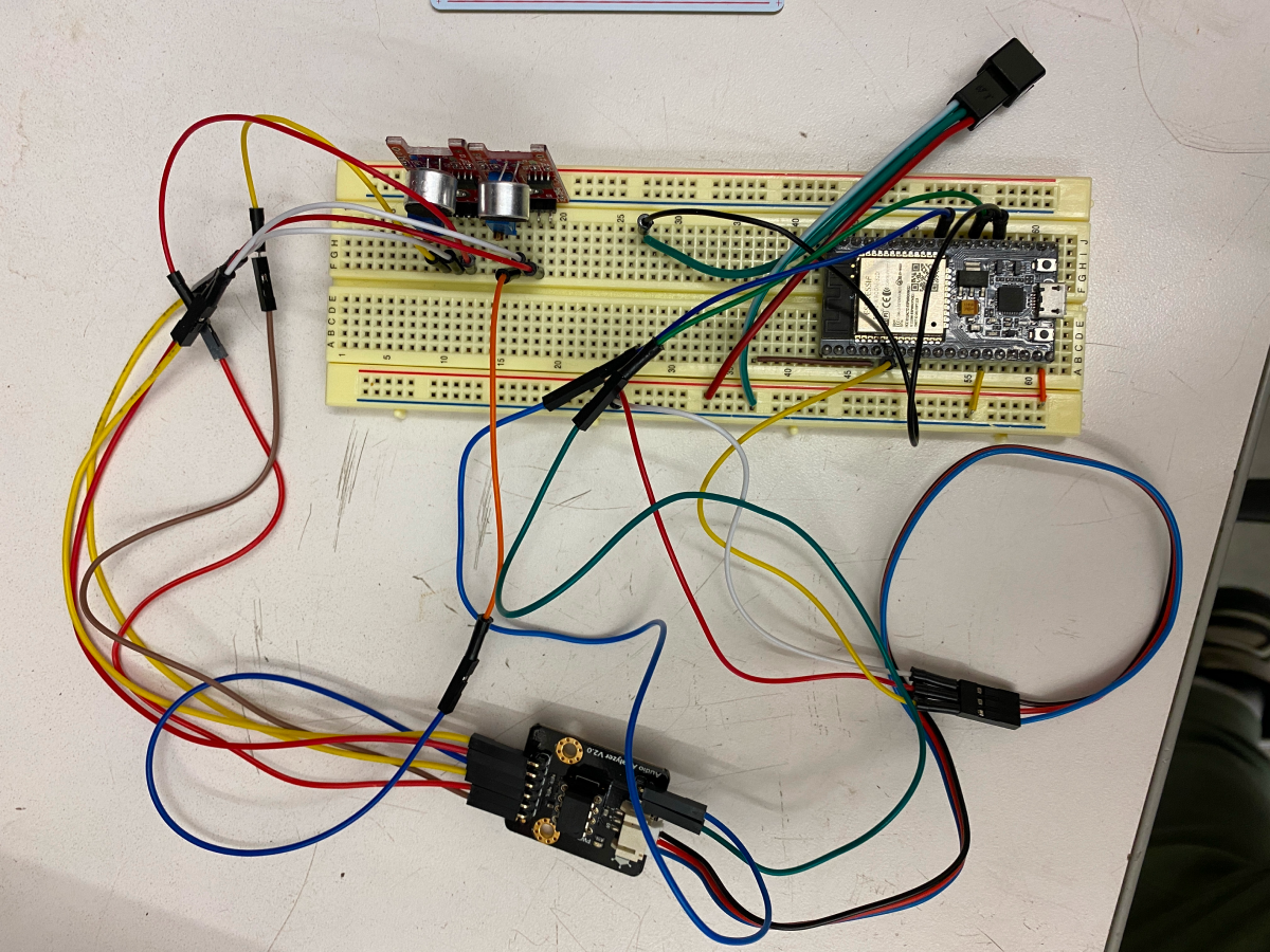
I started with prototyping the electrical work on a breadboard. Two microphones are hooked up to a module that breaks down the input into seven frequencies. These frequencies are processed by the ESP32 microcontroller for various functions.
I was able to detect varying levels of frequencies on my computer console, and for proof of concept, I connected it to a full strip of LEDs.
02
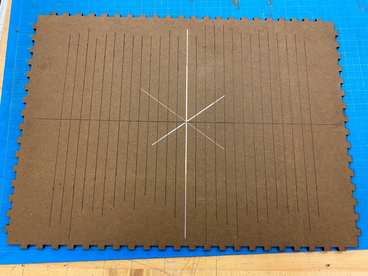
I laser cut an open-faced box that will connect with finger joints. I wanted a dark, relatively inexpensive material, so I chose duron.
I wanted to utilize as many of the 600 LEDs I had, but I needed a line of symmetry in the middle, so I measured out a 27 x 22 grid. Evenly spaced horizontally and vertically, each LED would be separated in individual squares.
03
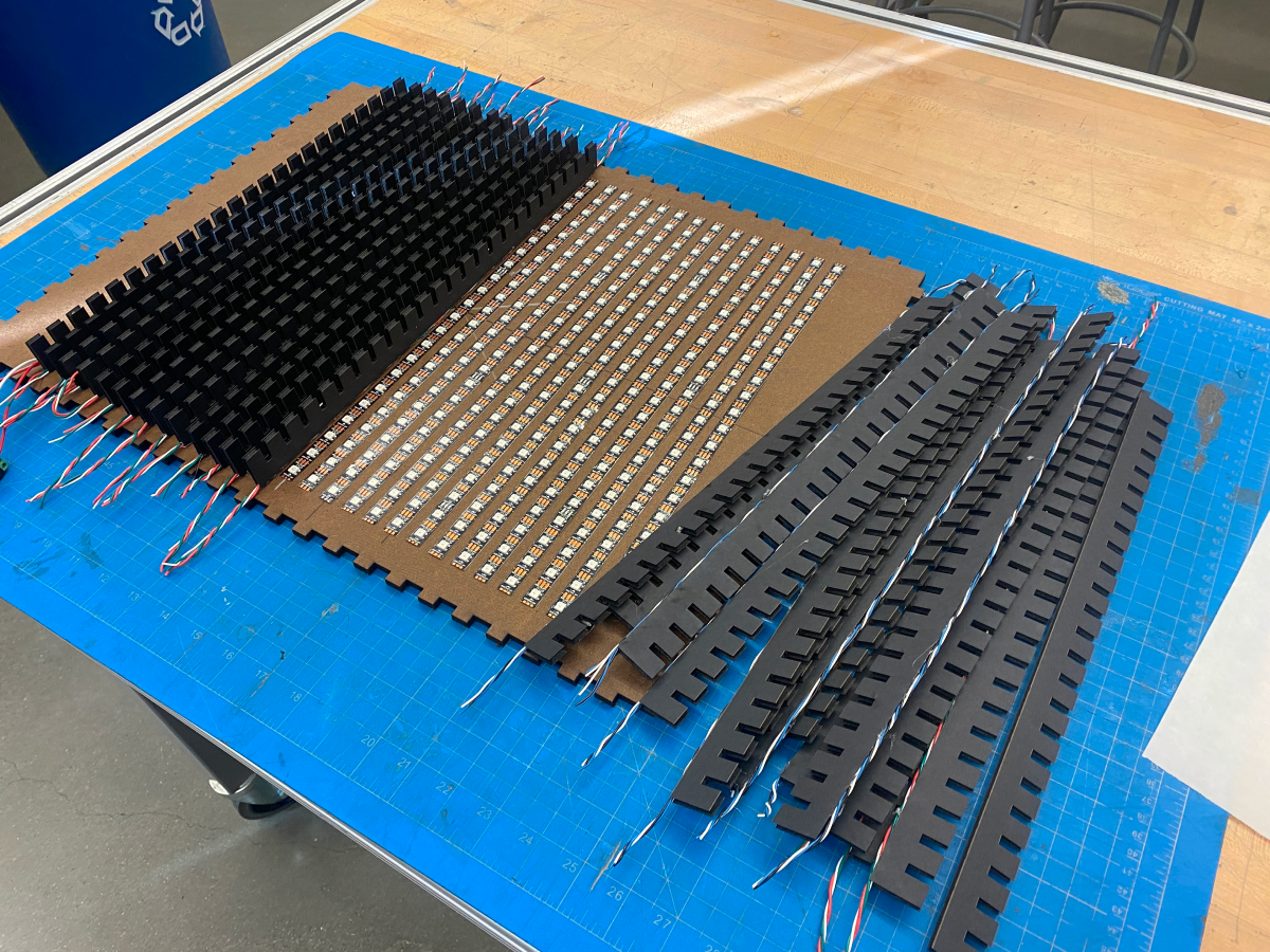
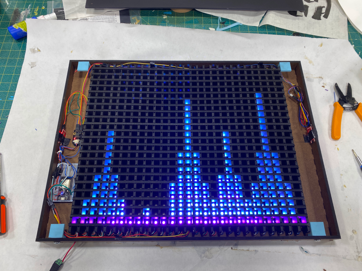
I adhered the strips of LEDs, making sure to keep everything properly spaced. I also laser cut pieces of dividers that connect to form a grid system, and I glued it onto the back panel.
To make it easier for me to code later, I needed to wire the LEDs from the top to the bottom of adjacent strips. In order to keep everything neat, I hid the wires underneath the foam dividers.
04
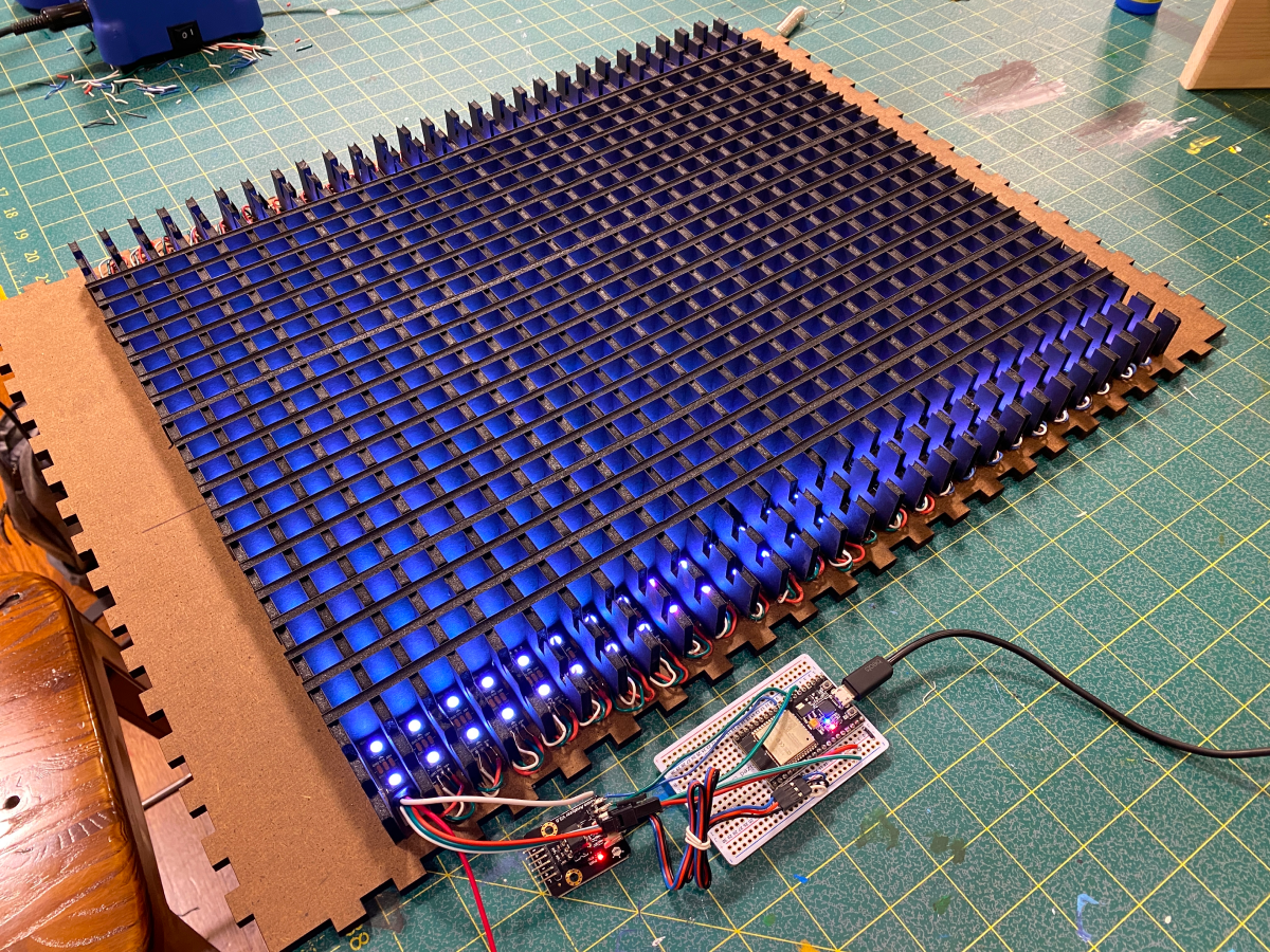
I completed the grid system to isolate each individual LED in its own square. I then soldered the LED strips together to form a complete matrix of 594 LEDs.
I later made some slight adjustments to the circuit to supplement additional power to the right half of the display.
05
I glued the outer walls of the frame together and laid out the electrical components in their final position. I also 3D printed my own brackets that I could use to attach the front acrylic piece to. Inside each one, are heat-set threaded inserts. This allows me to unscrew the brackets from the outside, giving me access to the inside at any point just by removing the front acrylic.
Then, I uploaded my custom music-reactive code to the microcontroller— finally bring it to life.
06
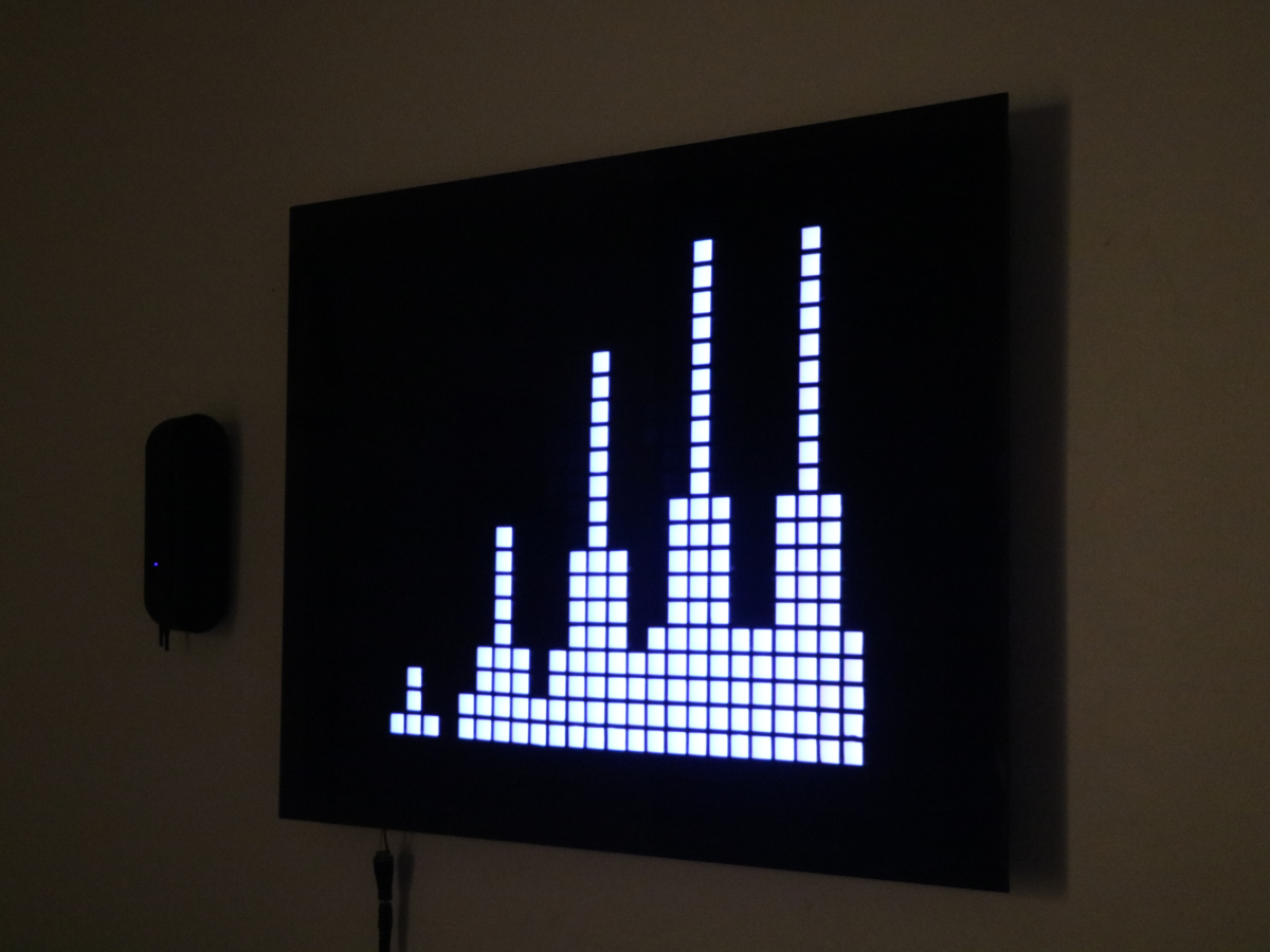
I epoxied the acrylic to the brackets, creating a sleek finish with a secure fit. Made with a light-passing black acrylic, the display is perfect for brilliantly showing just the lit-up squares.
This project culminates every developed skill seen in my past work. I'm incredibly proud of the result, and because of the ESP32's wifi and bluetooth capabilities, the display has endless possibilities.
07
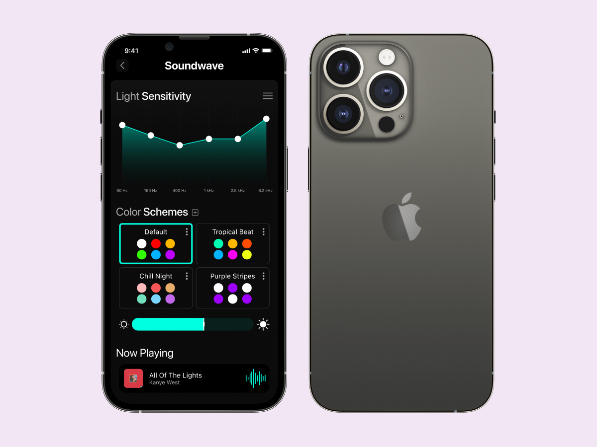
I wanted to be able to control the display without having to remove the front panel and edit the code each time, so I thought of an app that could make total use of the LEDs and ESP32. With three different modes, I would be able to use the display for music, ambient light, and simple retro games.
I had to keep in mind the limitations of the display while designing, since the number of LEDs in the matrix was an obvious constraint.
